Pipe Fitter Isometric Drawing Guide
Understand Industrial Piping Drawings, Symbols, Dimensions and Pipe Layouts
A piping isometric drawing (often abbreviated as an "iso") is a 3D-style pictorial representation of an industrial piping route drawn on a flat, two-dimensional sheet. Rather than showing true perspective where distant lines shrink, isometric drawings use uniform 30-degree angles to communicate precise pipe coordinates, component locations, elevations, fitting orientations, and fabrication cut lengths.
This practical educational guide by Ashtar Trade Test & Technical Training Centre is crafted to help beginners, technical students, and trade test candidates understand how to read piping symbols, interpret dimensions, calculate takeoffs, and connect blueprint details with actual workshop pipe assembly. Note: Drawing conventions vary across industrial projects and engineering standards; always verify the project legend.
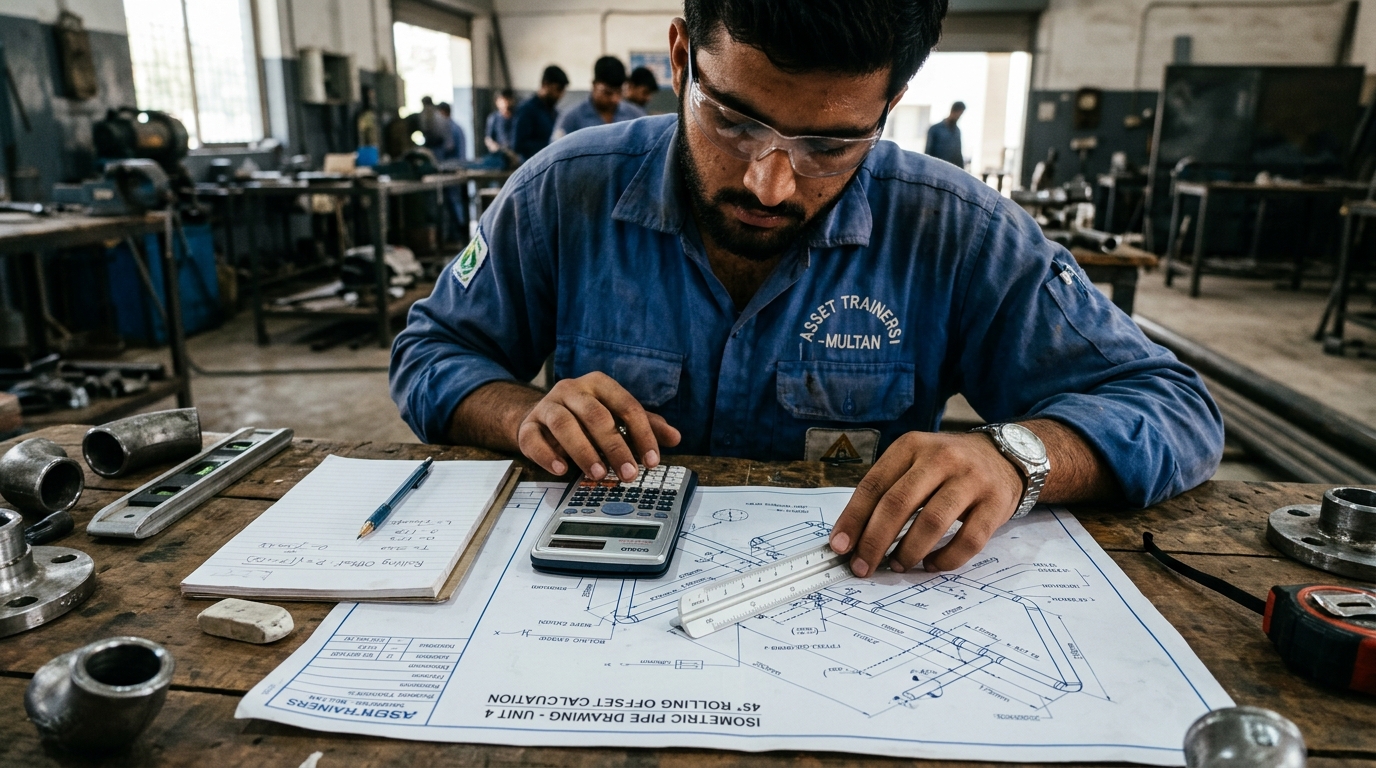
Sample Piping Isometric Blueprint Reading
Trainee reviewing pipe route coordinates, elevation marks, and Bill of Materials at Ashtar workshop.
What Is a Pipe Fitter Isometric Drawing?
In piping design, complex pipelines twist through industrial plants, changing direction, climbing over structural beams, and connecting to pumps, vessels, and tanks. Standard two-dimensional views (like a plan view looking down) struggle to show three-dimensional elevation changes on a single sheet.
Why an Angled View?
An isometric drawing tilts the coordinate axes at 30 degrees to the horizontal. This lets the drafter show the pipe's length, width, and vertical elevation all on a single flat page without lines converging toward a vanishing point.
How Fitters Use the Drawing
A pipe fitter uses an isometric drawing to fabricate pipe spools in the workshop. The drawing tells the fitter which pipe diameter and schedule to cut, which elbows and tees to bevel, where flanges weld on, and how to verify overall spool length against specified dimensions.
Not Just a Schematic
Unlike a Process Flow Diagram (PFD) or P&ID which only shows process logic, an isometric drawing is a fabrication drawing containing explicit dimensions, line numbers, weld symbols, and component part numbers.
Technical Comparison: Plan View vs. Isometric View
Cannot show vertical elevation rise without symbol overlays. Difficult to judge 3D spatial routing.
Vertical and horizontal direction changes are clearly visible on a single drawing.
Illustrative comparison representing the same pipe arrangement.
Understanding Isometric Drawing Directions
All isometric drawings are built upon three primary axes. Understanding how north, south, east, west, and vertical elevations align on the page is the first critical step for every pipe fitter.
The Three Isometric Axes
30-degree isometric axes with vertical axis at 90 degrees.
Vertical Lines Always Run True Up and Down (90°)
Any pipe moving vertically up or down is always drawn as a strictly vertical straight line on the page.
Horizontal Runs Follow 30-Degree Lines
Horizontal pipes running North-South or East-West are never drawn horizontal on the page; they are tilted along the 30-degree isometric grid lines.
Always Find the "North Arrow" First
Every piping isometric has a North Arrow block in one corner. Some projects place North pointing toward the top-right, while others place it top-left. Always establish the North reference before reading coordinates!
Common Pipe Fitting Symbols Explained
Fittings are represented by standard drafting symbols on isometric drawings. Review these 8 fundamental components.
1. Elbow (90° / 45°)
Function: Changes piping direction. Commonly drawn as an angled bend or intersection dot indicating a butt-weld or socket elbow.
2. Tee (Equal / Reducing)
Function: Creates a 90-degree branch connection. The branch can be the same nominal diameter (equal) or smaller (reducing).
3. Reducer (Conc / Ecc)
Function: Transitions pipe sizes. Drawn as a trapezoid indicating concentric (centerline aligned) or eccentric (flat top/bottom).
4. Flange Connection
Function: Provides a bolted mechanical joint for dismantling or connecting to equipment nozzles, valves, or meters.
5. Valve (Isolation / Control)
Function: Isolates or regulates fluid flow. Drawn as a bowtie symbol with a stem and handwheel indicator.
6. Pipe Coupling / Socket
Function: Joins straight lengths of small-bore pipe or connects threaded/socket-welded pipe sections.
7. Pipe Cap (End Closure)
Function: Closes off a dead end or future expansion branch. Drawn as a curved or flat cap welded to the pipe tip.
8. Pipe Support / Hanger
Function: Holds pipe weight, guides thermal expansion, or restrains seismic/vibration loads. Marked with tag IDs.
Understanding Dimensions in Piping Isometric Drawings
Isometric drawings are not drawn to scale. That is, a 10-meter pipe run is not drawn twice as long as a 5-meter run. Fitters must read the written numeric dimension callouts rather than measuring the drawing line with a physical ruler!
Centerline-to-Centerline Dimensions (C to C)
Dimensions on isometric drawings are predominantly stated from the centerline of one fitting to the centerline of the next. To cut the actual pipe length, the fitter must subtract the fitting takeoff distances!
Elevation Information (EL + / BOP / COP)
Elevations define vertical height relative to plant grade: EL +105.200m indicates centerline elevation, while BOP indicates Bottom of Pipe (critical for support placement).
Drawing Units & Coordinate Callouts
Check the title block to verify whether units are in millimeters (metric) or inches/feet (imperial). Never guess units!
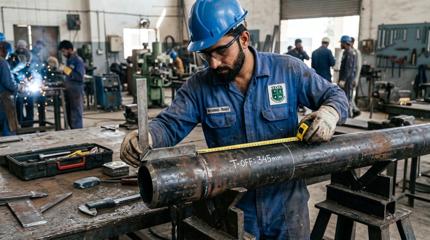
Blueprint Takeoff Calculation & Measurement
Trainee translating stated drawing dimensions into accurate pipe cut markings on steel pipe.
Understanding Pipe Routing in Isometric Drawings
Trace a sample illustrative pipe route from starting flange to destination branch, examining how direction and elevation changes are depicted.
Illustrative sample route demonstrating direction changes, elevation rise, branch takeoff, valve placement, and pipe size reduction.
The line begins with a bolted weld-neck flange connected to an equipment nozzle or vessel outlet.
A 90° elbow changes horizontal East direction into a strictly vertical riser climbing 800mm.
At the top elevation, a second elbow turns the pipe horizontally along the 30° North grid line.
A tee branches fluid downward to a secondary process line or drain connection.
An isolation valve allows maintenance shutoff. Flow direction and stem clearance must be maintained.
Transitions line diameter (e.g. from 4" down to 3") prior to final equipment tie-in.
Understanding Pipe Sizes, Schedules and Drawing Notes
A drawing graphic is only half the blueprint. The accompanying Bill of Materials (BOM), title block, and engineering notes contain the mandatory technical specifications.
Nominal Pipe Size (NPS / DN)
Refers to approximate inside diameter for sizes up to 12" (e.g. 4" NPS = DN 100). For sizes 14" and larger, NPS equals the actual outside diameter (OD).
Pipe Schedule (Wall Thickness)
Designations like Sch 40, Sch 80, or Sch 160 specify wall thickness and pressure capability. Thicker walls require heavier root bevel preparation.
Bill of Materials (BOM)
A tabulated item list on the drawing sheet detailing item numbers, component quantities, material grades (e.g. ASTM A106 Gr. B), ratings, and descriptions.
Revision Blocks & Notes
Always confirm the drawing revision (Rev 0, Rev 1, etc.). Fabrication must always proceed using the latest "Issued for Construction" (IFC) revision.
How to Understand a Simple Pipe Isometric Drawing (7 Steps)
Follow this systematic educational sequence whenever analyzing a new piping isometric drawing in the workshop.
Read the Drawing Title Block and Line Number
Identify plant area, unit number, line ID, fluid service (e.g. Steam, Hydrocarbon, Cooling Water), and design pressure.
Check the Drawing Legend and Units
Confirm whether linear measurements are in millimeters or inches, and review any special symbology used by the contractor.
Locate the North Arrow and Trace Main Route
Establish your compass reference and visually trace the main pipeline from source tie-in point to terminal nozzle.
Recognize and Catalog All Fittings
Cross-reference each drawn elbow, tee, reducer, and flange against the Bill of Materials (BOM) item numbers.
Review Centerline Dimensions and Elevations
Calculate pipe cut lengths by subtracting fitting center-to-face takeoffs and root gaps from the overall dimensions.
Identify Connection Interfaces and Support Points
Check field weld (FW) vs shop weld (SW) markers, flange pressure classes, gasket specifications, and hanger tags.
Verify Applicable Revisions and General Engineering Notes
Inspect project hold notes, non-destructive testing (NDT/X-ray) requirements, paint/insulation codes, and hydrostatic test pressures.
Common Pipe Fitter Isometric Drawing Mistakes
Avoid these frequent interpretation pitfalls during workshop training and practical assessments.
1. Confusing Plan vs Isometric View
Treating a 30° isometric line as a true geographical angle rather than a cardinal North-South or East-West direction.
2. Ignoring Drawing Units
Assuming millimeters when a project is drawn in decimal feet or inches, leading to catastrophic cutting errors.
3. Misidentifying Fittings
Mistaking a 45° elbow for a 90° elbow, or confusing concentric reducers with eccentric reducers.
4. Overlooking Drawing Notes
Ignoring critical notes specifying minimum cut lengths, field adjustment allowances, or special bevel angles.
5. Branch vs Main Line Confusion
Mixing up the main header pipe diameter with branch lines when reducing tees are placed in the circuit.
6. Estimating by Visual Line Length
Assuming that a drawn line that appears short represents a short pipe. Remember: Isometrics are NOT to scale!
7. Forgetting Fitting Takeoffs
Cutting pipe straight to the centerline dimension without subtracting elbow center-to-face or flange lengths.
8. Using Outdated Revision Sheets
Fabricating spools using an superseded revision sheet (e.g. Rev 0) when engineering released Rev 2 changes.
Why Isometric Drawing Knowledge Matters for Pipe Fitter Assessments
During foreign client trade tests (such as recruitment delegations for oil refineries, power plants, and fertilizer complexes in Saudi Arabia, UAE, Qatar, and Oman), examiners rarely test simple manual cutting in isolation.
Candidates are almost always given an isometric test drawing. The examiner observes whether the candidate can independently extract cut lengths, select the correct fittings from the material rack, bevel joints, orient two-hole flange levels, and assemble the pipe spool within tight dimensional tolerances (±1mm to ±2mm).
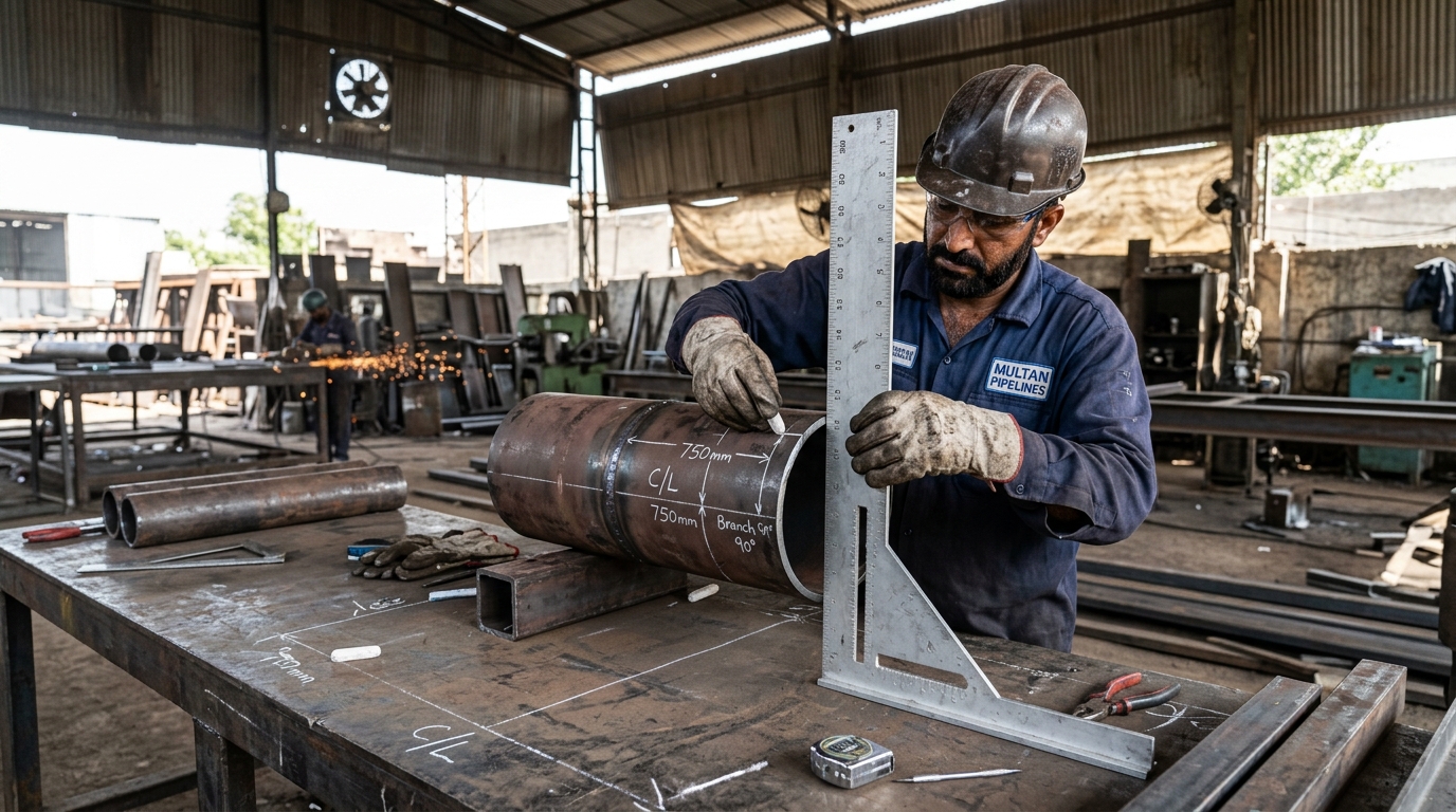
Practical Pipe Layout & Spool Fit-Up
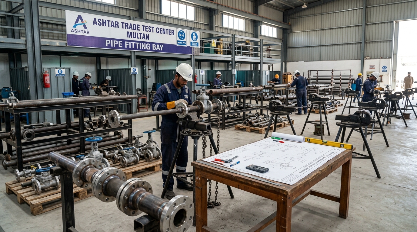
Translating blueprint drawing specifications into physical workshop assembly in Multan.
Learn Pipe Fitting & Drawing Interpretation at Ashtar Trade Test Multan
Ashtar Trade Test & Technical Training Centre is a dedicated technical testing and vocational preparation institute located in Multan, Pakistan. Our pipe fitting workshop provides trainees with hands-on practice under trade instructor supervision.
Hands-on Workshop Bays: Practice with pipe vices, wrap-around bands, beveling tools, and flanges.
Blueprint Reading Modules: Dedicated instruction in isometric symbols, BOM takeoff, and coordinates.
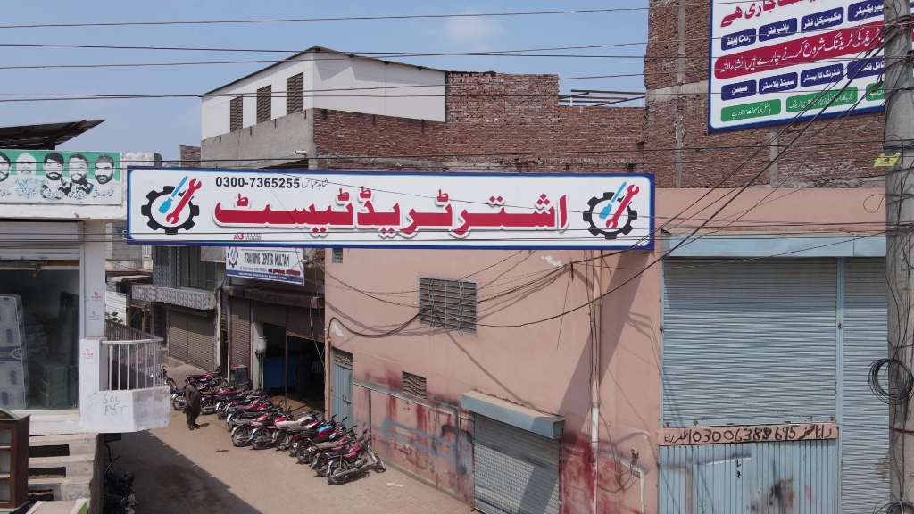
Physical Campus: Usman-e-Ghani Road, near Brite Hall School, Multan, Pakistan.
Inquiries Hotline: 0300-7365255 / 0300-7322762.
Pipe Fitter Isometric Drawing Learning Resources for Pakistan
This digital guide is freely accessible to technicians, apprentices, and candidates throughout Pakistan.
Whether you are studying from Multan, Lahore, Karachi, Islamabad, Rawalpindi, Faisalabad, Bahawalpur, Dera Ghazi Khan, or other industrial districts, mastering isometric drawings is essential for industrial piping trades.
Campus Notice: Practical hands-on workshop training, test bay rehearsals, and instructor coaching are conducted physically at our Multan institute on Usman-e-Ghani Road. We do not operate separate branch campuses in other cities.
Pipe Fitter Isometric Drawing FAQs
Clear, beginner-friendly answers to common questions about industrial piping blueprints and symbols.
What is a Pipe Fitter Isometric Drawing?
It is a 3D-style pictorial drawing of a piping system drawn on a 2D sheet using 30° grid lines. It communicates line coordinates, elevation changes, fittings, and cut lengths without visual perspective distortion.
Why are isometric drawings important in pipe fitting?
They provide complete fabrication data for shop-welded and field-installed spools—including cut lengths, fitting takeoffs, component ratings, and coordinate routing—before cutting pipe.
What is the difference between a plan view and an isometric view?
A plan view looks straight down from above and cannot clearly show vertical elevation changes on its own. An isometric view shows vertical, horizontal, and angled pipe runs all on one sheet.
Which fittings commonly appear in piping drawings?
Common fittings include 90° and 45° elbows, straight and reducing tees, concentric/eccentric reducers, flanges, valves (gate, globe, check, ball), couplings, caps, and pipe supports.
How are dimensions shown on an isometric drawing?
Dimensions are written along centerline-to-centerline dimension extension lines, showing linear lengths between fittings or elevation marks (e.g. EL +104.500m) above plant grade.
What do pipe elbows and tees represent?
An elbow represents a change in pipeline direction (horizontal, vertical, or angled). A tee represents a branch connection branching off the main header pipe.
How can beginners learn piping drawing symbols?
Start with core symbols (elbows, tees, flanges, valves), practice drawing isometric axes on grid paper, study project legends, and practice in a hands-on technical workshop.
Are all piping isometric symbols the same?
No. While core conventions are widely shared across international standards, company-specific drafting symbols and abbreviations vary. Always check the project legend block.
Can drawing knowledge help with Pipe Fitter Trade Test preparation?
Yes. Many employer delegation trade tests require candidates to read an isometric drawing, compute cut lengths, and assemble a test spool within strict dimensional limits.
Where can I inquire about Pipe Fitter training in Multan?
Visit Ashtar Trade Test & Technical Training Centre on Usman-e-Ghani Road, near Brite Hall School, Multan, or call 0300-7365255 / 0300-7322762.
Does every Pipe Fitter Trade Test include an isometric drawing?
Not every test is identical, as testing rubrics depend on individual hiring employers. However, industrial and overseas assessments frequently include blueprint tasks.
How can I contact Ashtar Trade Test Centre?
Call our admissions lines at 0300-7365255 or 0300-7322762, connect on WhatsApp, or visit our Multan campus during operating hours.
Learn to Understand Pipe Fitter Isometric Drawings
Explore the fundamentals of piping symbols, dimensions, component identification, and drawing interpretation. Contact Ashtar Trade Test & Technical Training Centre, Multan, for information about available Pipe Fitter training.
Ashtar Trade Test & Technical Training Centre